
GREI guide
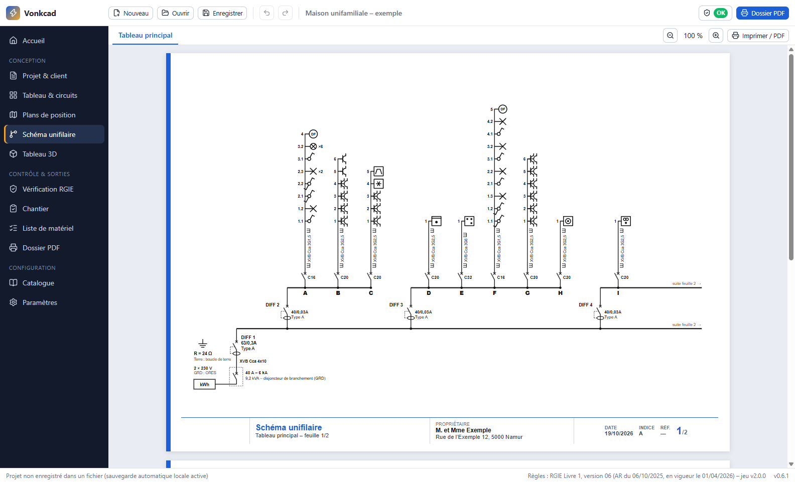
The single-line diagram under the GREI
For every new domestic installation, or one that is substantially modified or extended, the person in charge of the work draws up the single-line diagram. Here is what it must contain.
When is a single-line diagram needed?
The GREI (subsection 3.1.2.1) requires single-line diagrams and layout plans for every new domestic electrical installation, and for every substantial modification or extension of an existing one. The person in charge of carrying out the work draws them up.
For a modification or extension that is not substantial, a new single-line diagram is not required: a short description, dated and signed by those responsible for the work, is enough. The layout plan, however, must always show the current situation.
What the single-line diagram shows
Under subsection 3.1.2.2, the single-line diagram of a domestic installation shows at least:
- the characteristics of the wiring: type, cross-section and number of conductors;
- the installation method of the wiring;
- the type and characteristics of the residual current devices;
- the type and characteristics of the overcurrent protection;
- the switches, connection boxes and junction boxes;
- the socket outlets and lighting points;
- the fixed machines and appliances;
- the sources: transformer, solar panels, inverter, battery…
It also states the voltage and type of current, the name, capacity and VAT number of the person in charge of the work, the address of the installation, and the document’s number, version and date.
Marking: one letter per circuit, one number per point
Each circuit is identified by a capital letter. Each lighting point, socket outlet and control unit gets a number, in the order met when starting from the circuit’s protective device: A1, A2, A3…
The same marks appear on the layout plan: this is how the approved body checks that the installation matches the diagrams.
The symbols
The symbols to use are those in table 2.23 of the GREI. If an item is not listed, any other clearly identifiable symbol may be used, provided it is defined in the legend.
A multi-line diagram is also allowed if needed, with the same information and standard symbols.
Old parts
Any part of the installation whose construction began before 1 October 1981 and which appears on the single-line diagram is marked “old part”.
At the acceptance inspection
If the installation complies, the person in charge of the work and the approved body sign and date the single-line diagrams and layout plans. They are handed to the owner with the inspection report, for the installation file.
With Vonkcad
The single-line diagram draws itself, from the board
- Circuit letters and point numbers assigned automatically
- Cross-sections, installation methods, RCDs and circuit breakers always up to date
- Title block in your name, with your VAT number and the site address
- Symbol legend, A4 or A3 printing
Read also
The layout plan
The items to show, the letter-and-number marking, keeping it up to date.
The acceptance inspection
The documents to prepare, what the approved body checks, the report.
This guide summarises the GREI Book 1, 2026 version. Only the official text published by the FPS Economy is authoritative.
Your next file, with Vonkcad
Single-line diagram, layout plans, GREI check and PDF file: everything is linked in one project. Free during the beta.